Contact Email

My contact email: 1tgoding@gmail.com

Thursday, May 18, 2023

Rear Cabin Wall and Seat Back Frames.

 Rear Cabin Wall install.


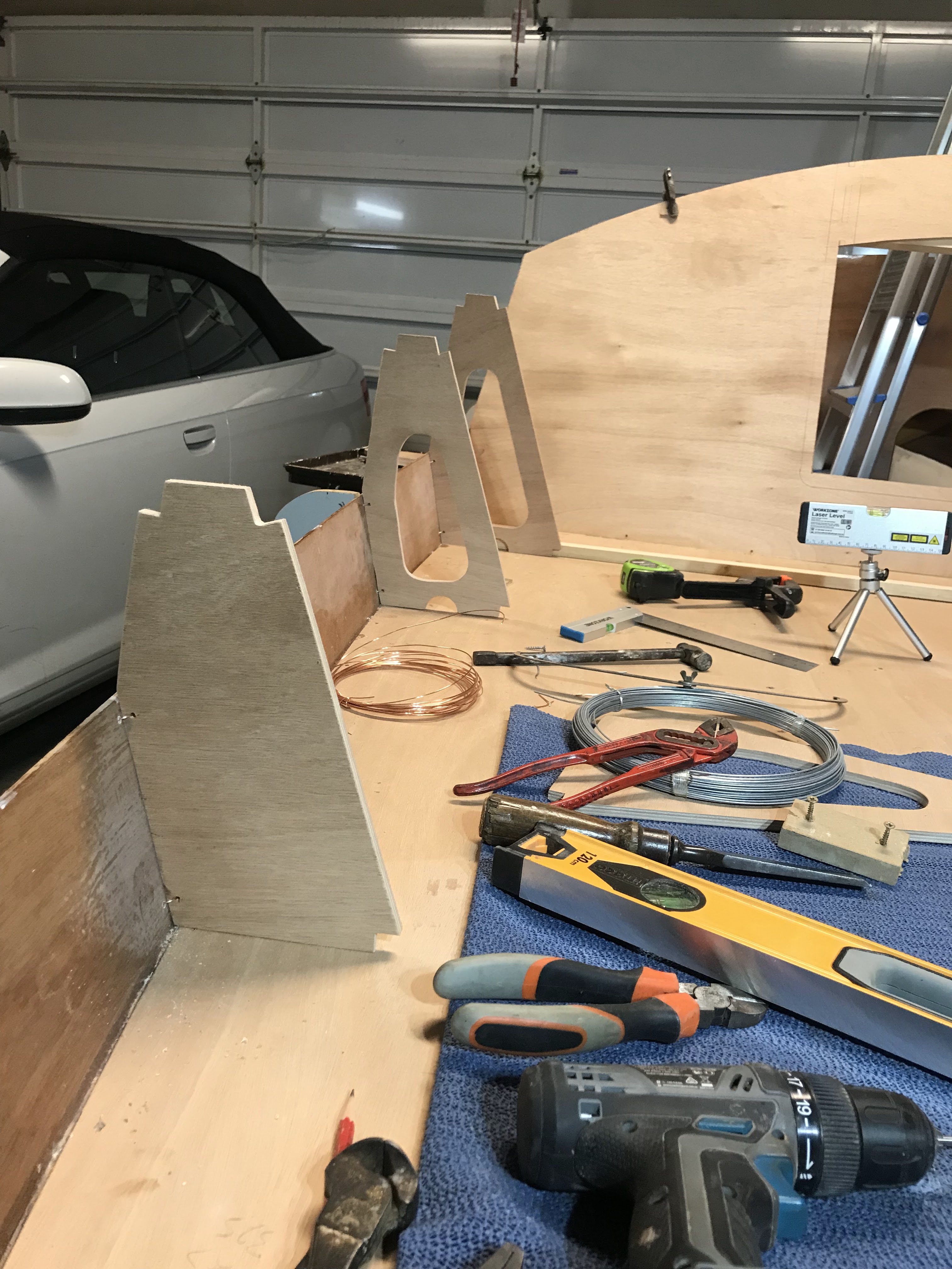
I spent a couple of hours tracing the rear cabin wall and seat back frames onto 9mm ply. After a bit of jig saw work the rear cabin wall was stitched to the cockpit seat. I used clamps on the hull sides to temporarily hold the cabin wall in place.  


The correct angle was secured by screws through the hull sides and a temporary cleat screwed on top of BH 2 and the rear cabin wall.


Seat Back Frame Install.


To locate the position of floor 6 I used a laser level from the hull bottom and transferred it to the top of the hull sides.


The seat back frames were stitched in place above floor 6, BH 7 and BH 8.


To align the frames athwartships a length of timber was clamped at the base of the frames. 


A carpenter's square ensured the frame was perpendicular to the cockpit prior to stitching the frames to the hull sides.


Friday, May 12, 2023

Flush Timber Hatch Lids

 Now the cockpit floors are installed it's time to work on the hatch lids.


I need to consider the following when constructing the hatch lids:
  • They need to be hinged.
  • They need to be reinforced so they can handle the weight of a person standing on them.
  • They need to be waterproof.
  • They need to be able to be locked.
Firstly, the cockpit floors around the hatches need to be trimmed and the edges rounded over.


I used a "Trimming" router bit to clean up the cockpit floor overhang.


And a 6mm round over router bit for the edges.


A router jig is made for the lid hatch lock.


The routed recess allows the thicker section of the hatch lid to neatly slide down.


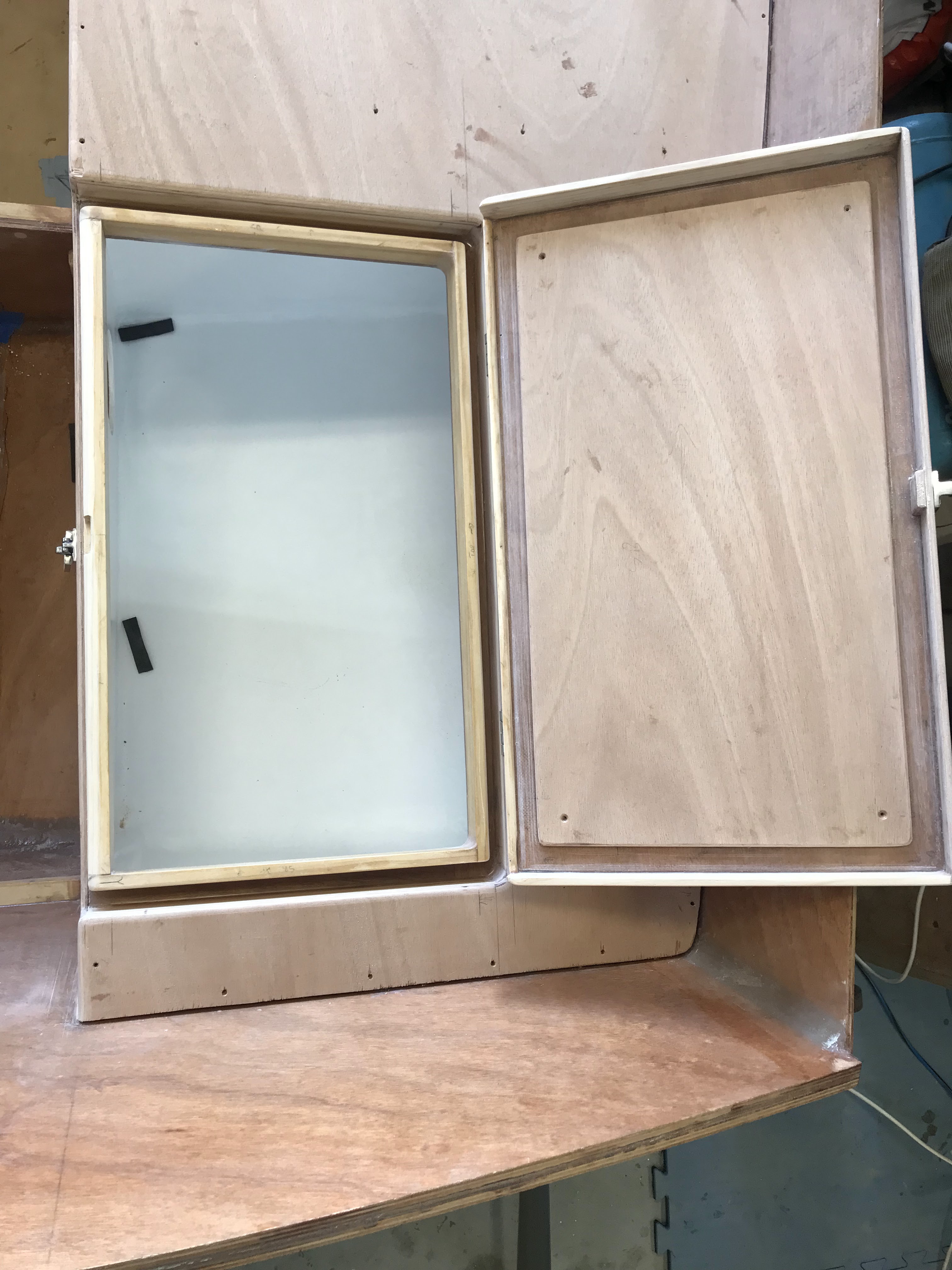
Each Hatch lid consists of 15 parts including hardware. The 6mm ply lid is reinforced with a slightly smaller 6mm thick section laminated to the underside resulting in a strong 12mm thick lid. The reinforcing section is smaller so as to provide a gap around its circumference for a 2mm thick rubber seal.
All the components of the lid will be epoxy glued together and temporarily held with screws.
The hardware consists of 2 hinges and a lockable latch. The hinges will be fastened on top of 4mm shims which for decorative purposes will be 3mm larger than the hinges and provide a total of 10mm of ply timber beneath the hinges for fixing screws.

This has been an exciting mod requiring considerable planning, engineering, time and patients.


Gluing and screwing the sections together.


The hatch lid is sanded smooth, the edges rounded, and the hinges and latch are installed.


After some small adjustments the hatch opens and closes smoothly.


Here you can see the gap around the circumference of the lid where a 2mm thick rubber seal will be glued in place.


This pic shows the drainage channel around the hatch opening that will direct water into the footwell and then into the sea.


The shims under the hinges are both decorative and provide a 10mm thick bedding for the screws.


Wednesday, May 10, 2023

Cockpit floor Install

Prior to installing the SB cockpit floor, I threaded the centerboard pull rope into the centerboard case and over the round nylon pully. Cellotape was fixed to the opening at the top of the centerboard case to prevent epoxy running into the centerboard case.


The lower hull area and cleats are masked up.


The underside of the cockpit floor is masked up.


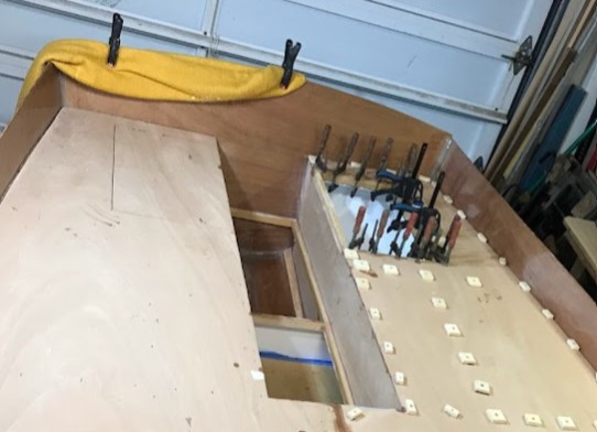
And finally, the SB cockpit floor is glued into place with temporary screws and clamps.


Likewise, the port cockpit floor is glued and clamped in place.


Now I'm qualified to say like many builders have previously:

"I can sit on the cockpit of my boat".

How good is that!


Because the footwell space was widened I added two additional cleats athwartships to provide extra strength for the footwell floor. 


So that's another milestone completed, it's quite exciting how one feels when completing the different build stages.

Now it's time to work on the flush timber hatch lids. I'm excited to complete this mod as it involves hinges, locks, reinforcements and most importantly the lids need to be waterproof to keep the lazarette areas dry.


Tuesday, May 2, 2023

A couple of jobs before installing the cockpit floor

 Only a few more jobs to be done before I can glue the cockpit floors in place.


 As I had previously drilled, and epoxy filled a larger hole in BH7 and the forward blocking timber of the centerboard case I only had to drill the shorter 16mm hole and 9mm hole through the centerboard case for the centerboard sheave components.


The round nylon pulley is located in the centerboard case between the shims.


A hex head bolt is located in the centerboard with a dome nut. Marine silicon is applied to the washers and bolt heads to make waterproof.

Monday, May 1, 2023

Painting Lazarette & Cabin Area

Time to paint the hull areas below the cockpit floor.

I found that when I painted the lower hull and bilge area it required quite a few coats to cover the dark colored plywood. Whilst Bote-Cote epoxy is suitable as undercoat it still leaves the plywood a dark timber color. So, after discussion with Scott at Boat Craft NSW it was suggested to use Bote-Cote "Flowcoat" as an undercoat. The advantage of this is the "Flowcoat" is a one-to-one mix, cheaper in cost than the polyurethane topcoat and covers the darker plywood color.

The Lazaret areas

 UNDERCOAT


The pic shows the lazarette area after one coat of "Flowcoat". Good coverage and a good base after a single coat.


FIRST COAT


After a light sanding the first coat of polyurethane topcoat is applied and provided good coverage, hopefully the area will require only one more coat.


SECOND COAT


A second coat is applied, and its perfect, no further coats required. The lazarette areas are finished.


Before installing the cockpit floors the remaining area forward of BH 8 has to be painted. As many builders have previously advised it is much easier to access this area now.


The undercoat is applied.


First coat.


Second coat and it looks good.


Now the painting has dried it's time to install the larger cleats supporting the cockpit floor.


Saturday, April 15, 2023

Speaker Install and Speaker Boxes

 Mod 4: Speaker Installation.

I read in Sun Monkey Island blog a mod for the radio speaker location. I didn't want to clutter up the forward storage area and decided to locate the speakers in BH 8. (Thanks to the builder who gave me this idea). It's much easier installing this prior to the cockpit floor install.


The speaker boxes will mount aft of BH8 in the lazarette area. This will protect the speakers from gear stored in the lazarette area, corrosion to the speakers and water getting into the cabin area.


The boxes are glued together.


...and trial fitted.


The speaker template taped in place on BH8.


...and the holes cut out.


The speaker boxes are glued in place, holes for the wires are drilled in the back of the boxes and because the speaker boxes are enclosed and airtight I drilled a larger hole in the front of the enclosed speaker box through BH 8. I believe this hole is to prevent the lower frequencies getting trapped and enhance bass response. I'll play some Led Zeppelin and test it out.


Thats the end of Fourteen months of construction


Saturday, April 1, 2023

Flush Timber Hatch Frames

 Mod 3: Flush Timber Cockpit Hatches.

I decided to build flush timber hatches where the sides of the hatch lid sit inside Chanell's that drain directly into the footwell.

Smaller cleats (30mm deep x 12mm wide) were trial fitted athwartships between the footwell side and the existing cleat between BH 8 and the transom. These will form the drainage channel. The base of the channel is cut from 9mm ply.


The outside channel cleats are glued to the 9mm bases, but the complete unit is not glued in at this stage.


The port & starboard units are removed for cleanup.

The inside channel cleats are cut 2mm lower than the external channel cleats, this is to provide space for a rubber seal.


The inside channel cleats are glued onto the 9mm base.


The clamps removed and the units are cleaned up.


The drainage units are glassed all round for strength.


Here is a close up showing the end cleat glued to the 9mm ply base.


To ensure the water drains towards the cockpit the base of the outside sections of the channels needed to be slightly higher than the interior sections. To achieve this, on a level bench I lifted the inside sections up by 3mm. Warm epoxy was poured into the channel over the 9mm ply base until it leveled out. when hardened and laid flat the outside sections were 3mm higher than the interior exits thus allowing water to flow into the cockpit.


The drainage units are installed by the following step by step process.


Firstly, the cockpit footwell sides are cut down that will form a recess for the front of the lazarette lid to sit.


Larger cleats are glued onto the footwell side walls. The cleats are deeper to support the drainage units and any weight on the lazarette locker lids. This pic shows the drainage channels through the footwell side walls that allow water to flow back to the sea.


The drainage units are glued in place.


The Lazarette areas are ready for fillets, glassing, cleanup and painting.