Contact Email

My contact email: 1tgoding@gmail.com

Sunday, December 31, 2023

Cockpit Footwell Floor Installed

 Well, another small part of the project completed. 


I left the installation of the footwell floor to last to enable easy access to run the electrical wiring through the 25mm conduits. 

I also installed two extra athwartship cleats to provide additional support for the footwell floor.


The footwell floor was sealed on the underside and holes marked and drilled in place ready for the temporary screws.


The temporary holding screws are prepared, and the cleats are covered with epoxy glue.


Finally, the floor is secured in place.


Friday, December 29, 2023

Electricals

 Time to run some wires. 

When designing the wiring run, I considered the following:
1) I did not want wires visual in the cabin area.
2) The wiring harness needed to include power for the following: DC power outlets, cabin lights, Nav lights, stereo speaker, GPS/Fishfinder power and transducer, bilge pump and future solar power and motor charging wires.


I split the wiring into two conduits that run from BH2 under the floorboards to the junction boxes. The conduits run through the enclosed buoyancy area under the cockpit foot well. The conduits are sealed with silicon where they pass through BH's to ensure the buoyancy chamber is airtight. A further conduit was installed athwartships to link the two junction boxes. 


I made the junction boxes from 6mm ply. They are fully sealed units with clear Perspex fronts and screwed to the transom.


The wiring runs up into the port and starboard aft seat back storage areas and then forward through conduits to the main cabin.


To reduce voltage drop for DC power and the main earth connection I used larger diam wires (4.5mm diam) from BH2 through to the junction boxes in the lazarettes. The larger wires continued forward to the cabin area. As the cabin and Nav lights are all LEDS I reduced the wiring from the lazarette area to the forward cabin area to 2mm diam.

All wiring was twin core tinned marine grade and to reduce doubling up of negative wiring I only ran positives for the Cabin and Nav lights. I also ran nylon pull chords with the wiring harness so I could pull through any future wiring.

Thursday, December 14, 2023

Speaker Install

April 2023's post covered the construction of two ported speaker boxes built in the lazarette area aft of BH 8. Ports are used to produce a higher and deeper bass response (should make led Zeppelin sound pretty cool)

Time to install two GME (GS520 110 watt, 163mm Dia flush mount speakers.


Wires are run from BH 2 through conduit under the cabin floor to the electrical connection boxes on transom and then through to the speaker boxes in the lazarette area.


The boxes are filled with sound deadening/dampening wadding.


The speakers are screwed in place and the covers installed. can't wait to hear how they sound.


Wednesday, November 8, 2023

Cockpit Seat Backs & electricals

 It's time to finish off the cockpit seat backs.


The storage lockers are undercoated.


Three coats of "Botecoat" white paint completes the seat back storage area.


I give the
inside face of the 6mm ply seat back three coats of epoxy and the forward storage section is painted. The area is ready to be closed up now (almost)


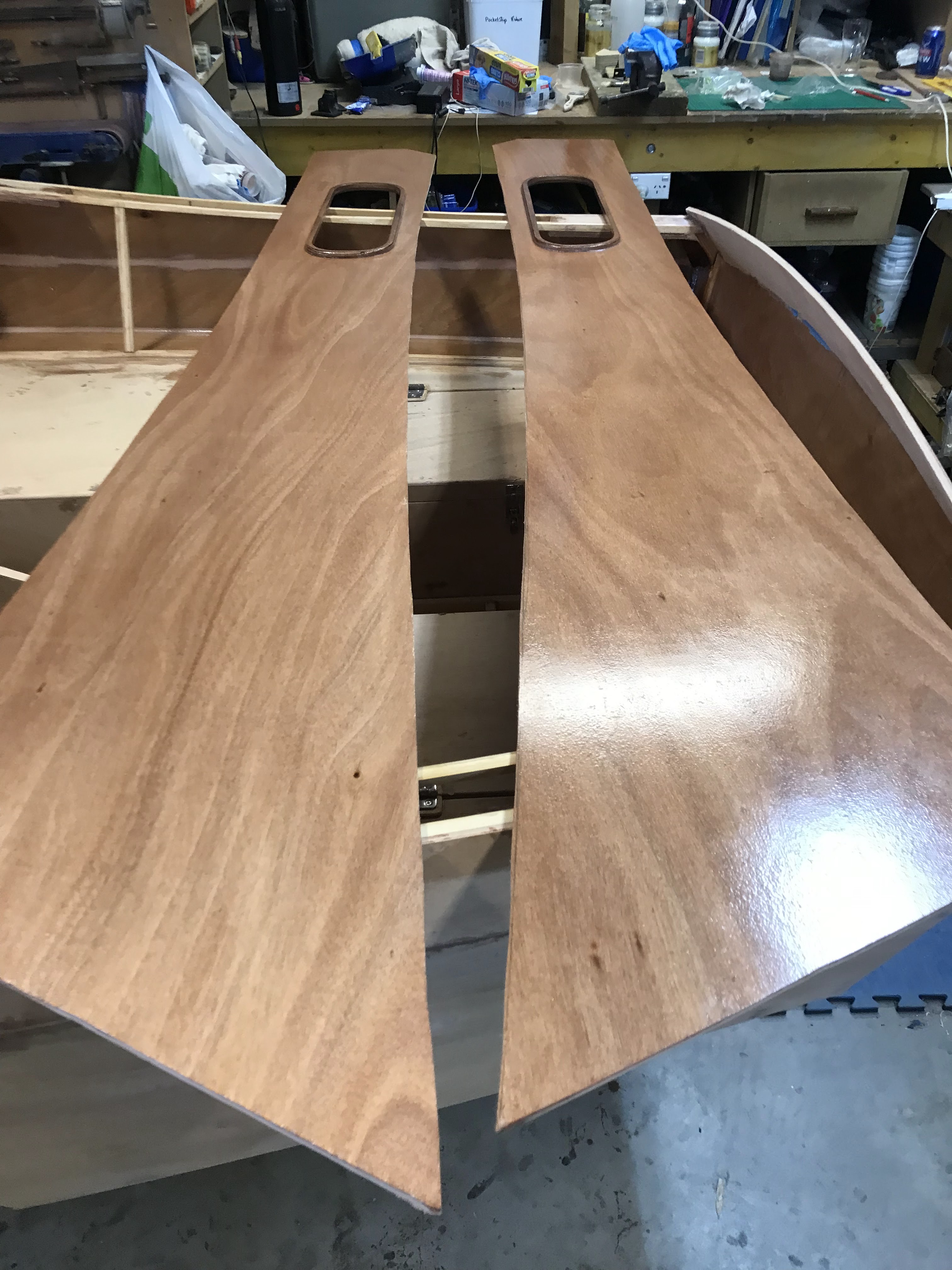
The seatbacks are glued in place...........


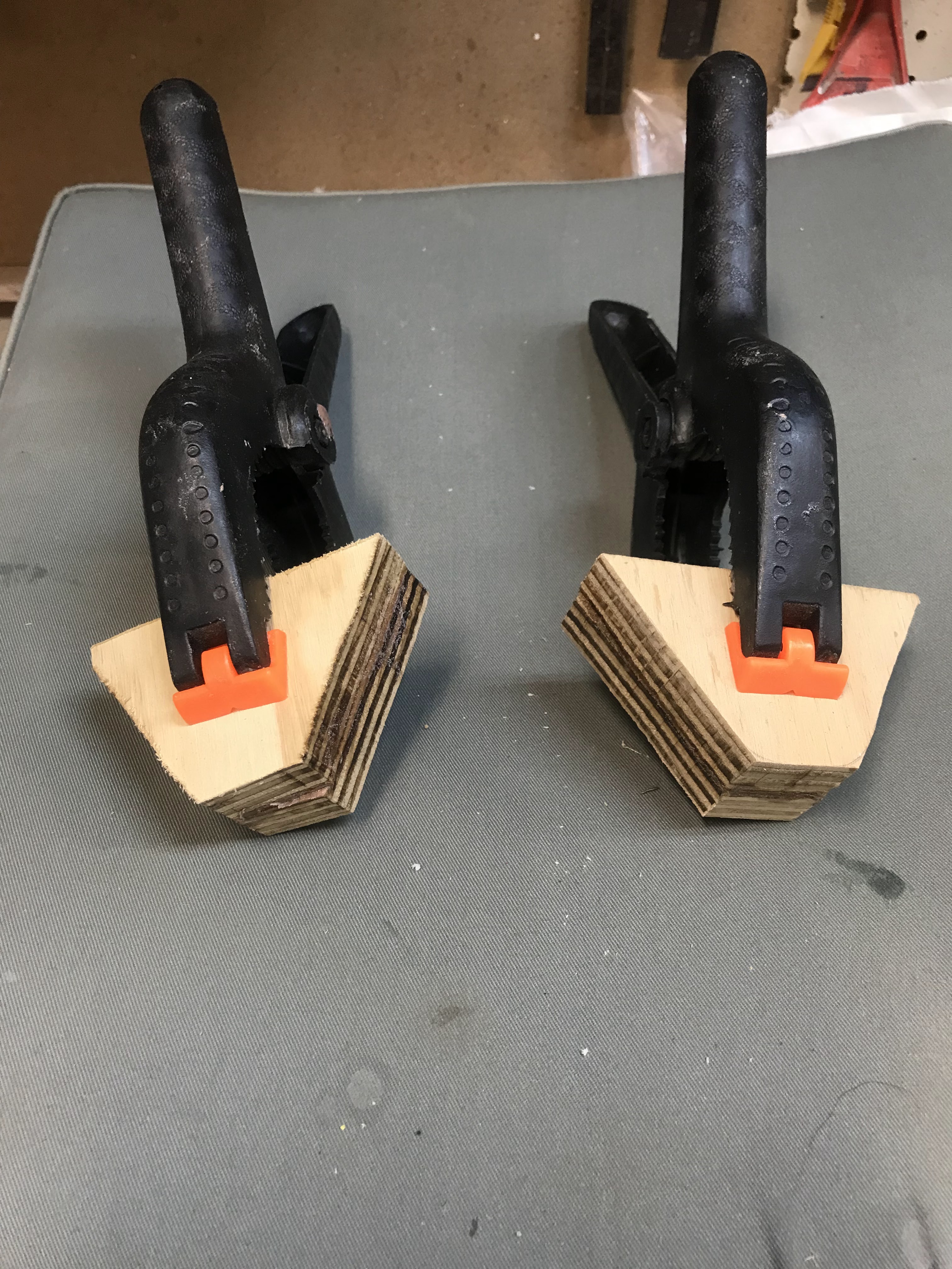
I use clamps and temporary screws to hold the seat backs in situ until the epoxy sets.


After cleaning up the seat back sides flush on top and before installing the last piece (the seat back deck) While I had access, I decided on another mod......


This mod is electrical, and I considered a number of things:


Firstly, I screwed cable ties that are in a loop to secure the electrical wiring through the locker space.


The very aft looped cable tie was quite the challenge. I improvised with some very long drill bits, very long screw drivers and blue tack to hold the screws onto the bit.   It would have been much more difficult if the seat back deck was glued in.


I also wanted to be able to light up the storage area, have USB DC power supply for mobile phones and iPad, switches and be able to see the current state of voltage. 


So, in the forward section of the port storage locker, I designed a small panel that would house all the items pictured below.


The area is protected from the elements, visual, provide easy access to the USB plug and switches and have the ability to be removed when required.


So firstly, I knocked up a cardboard template.


I trimmed and fitted the template several times before I obtained a neat finish.


Here is the final template held together with masking tape.


The template sections are traced onto 4mm ply, hot glued together and trimmed to fit. Epoxy fillets are laid on the inside to hold the unit together.


Holes are cut for the meters and switches and the unit given a protective coat of epoxy.


Here are some more views. 


This view has a great background.


An aluminum angle is used to secure a courtesy LED light which will be screwed to the very top of the switch section (as shown in pic below). This location will indirectly light up the storage area but not shine directly into my face. If required, it can be modified to a red color for night-time use.


The panel is painted, electrical outlets and two switches installed, one is a spare and the other turns both port and starboard locker courtesy lights on simultaneously.


Wiring is run from the port side lazarette chamber up into the storage area and connected to the panel. I used tinned copper electrical wire, 2mm for the LED lights and 4mm for the power. 


Additional wiring is also run from the Port lazarette chamber to the forward storage locker near the aft cabin BH via the 25mm electrical conduit. These wires will connect to the compass NAV light and provide cabin lights and DC power outlets into the main cabin. 


Now all the wiring is run and neatly cable tied together it's time to install the panel.


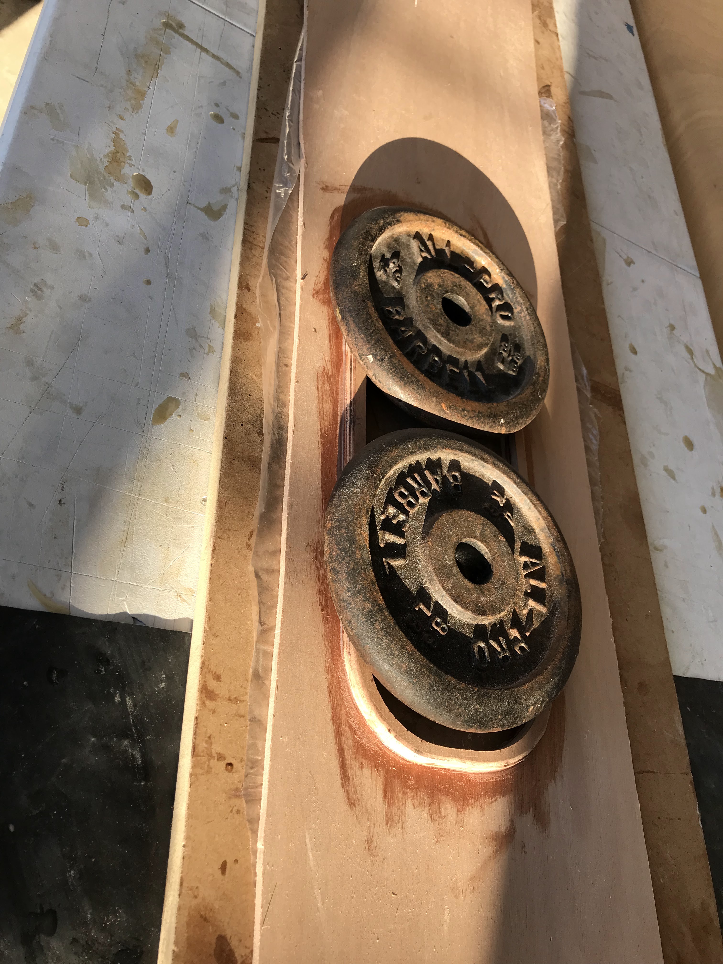
The port seat back top is glued and held in place with weights.
Next is the starboard side......that tomorrow's project. 


Friday, November 3, 2023

The Boom Gallows Part 1.

 The Boom Gallow Bases:

I decided to install the boom gallows bases and poles prior to installing the seat backs. It is much easier to build, install and paint this area without the seat backs in place.


For the bases I laminated two pieces of 18mm ply. 


After the epoxy dried, I shaped the pieces to fit the contour of the hull side.


Next step was to ensure the boat is level fore and aft and athwartships. As my workshop has a very slight slope, I used thin ply under the wheels to level up the boat.


I temporarily sat the 25mm stainless steel gallow poles on top of the laminated base just in front of the seat top blocking and held it in place with sticks and wedges.


The pole was levelled fore and aft with two spirit levels clamped to the pole. 
The poles circumference was traced onto the laminated base section.


Using a 25mm Forstner bit I drilled a hole through the upper blocking. Miner adjustments were made with a small drum sander.


The pole is inserted through the hole and vertically levelled again with two spirit levels.....


.... then held in place with very thin wedges.


The pencil line traced onto the laminated base was checked for accuracy and the laminated base location was marked onto the cockpit floor and hull side. 


Using a drill press, a 25mm hole was drilled into the laminated block forming the recess for the SS gallows pole to sit.


As mentioned earlier I planned to install the stern navigation light on the port aft side of the boom gallows. The wire to power the LED Nav light will run up from the lazarette area through the stainless-steel gallows pole and out through the boom gallows.


To do this I drilled a 6mm hole through the laminated base and then through the cockpit floor.


The epoxy on the cockpit floor and hull side is scored in preparation for gluing. 


The 
laminated base is now epoxied glued into place. The pole is inserted (but not glued) to ensure everything lines up correctly, vertical levels are checked again with spirit levels and a clamp holds the section in place until the glue dries.


Filets are laid and reinforcing cloth rolled on wet on wet.


Thursday, October 12, 2023

Cockpit Seat Backs

 To ensure a neat fit I decided to use cardboard templates on the forward and aft end of the cockpit seat backs.

When overlaying the cardboard templates onto the paper plans a slight difference can be seen.


The cardboard templates are located in position tight against the transom and the aft cabin BH. I hot glued the templates with thin plywood strips this provided the exact length required and eliminated any gaps that some builders have experienced in the past.


The additional time taken results in a neat fitting cockpit seat side. A very good result.

The next step was to cut out the seat back rings used as stiffeners behind the seat back storage area.


A small curve is routed on the inside edge of each ring.


The rings are used as templates to cut out the storage access holes....


.....glued and held in place with weights.


To seal the inside face three coats of epoxy are applied wet on wet. 

BUT before I glue it in place, I have a couple of mods.

The first mod is a storage area in the first buoyancy chamber aft of the cabin BH with access from inside the cabin area. The second mod is to add electrical conduit through the foam buoyancy chambers from the cabin BH to the aft seat back storage area. This will provide future electrical access for things like the transducer lead and power to a chart plotter, USB/Cig socket DC power outlets, light power and BH compass backlight power. This will eliminate visual wiring inside the cabin area.

I would welcome any comments, suggestions or thoughts re these mods, send me an email listed at the top of the page or via the "Contacts Form" above on the right.

Mod One "The Storage Area"

To provide access to the storage area I drilled three holes using a large hole saw and a Forstner bit.


The section is removed with a renovator tool.


A layer of cloth is epoxied onto the storage floor area.


Here is a view from the cabin area. I have some ideas on additional storage mods to the cabin BH, watch this space.


Mod Two "Electrical Access"


Using a Forstner bit I drilled 25mm holes into the seat back frames and the lazarette area. 


A length of 25mm electrical conduit is inserted through the seat back frames between the two storage areas. A smaller length of conduit is inserted through the cockpit floor and the lazarette area but raised above the deck to prevent water entering the lazarette area.


The conduit is sealed in place with silicon.


The smaller conduit is glassed into place.


Now the mods are complete there is still a significant amount of work required until I glue on the seat backs. 


A layer of cloth is epoxied onto the floor of both for and aft storage areas.


The whole area is given three coats of epoxy wet on wet to ensure it is well sealed and watertight.


Now it's time to make lots of mess. No matter how much you try you can't cut up polystyrene foam without small beads going everywhere.
I had collected foam packing and foam boxes for months, now it's time to cut it up and fill the buoyancy chambers. Don't underestimate this job, its very time consuming. If I had my time over again I would use expanding foam, much easier, much quicker and NO MESS.

Anyway, I feel better now I've had my rant. here are pics of the installed foam.