Contact Email

My contact email: 1tgoding@gmail.com

Sunday, February 4, 2024

Cabin Deck Top and BH2 Construction


The top deck construction involves installation of Carlins, Cleats, Dorade Boxes, Electrical, Top Deck and yes, a couple of Mods.


I decided to beef up the two 18mm x 25mm upper longitudinal carlins between BH2 and BH3 to 20mm x 30mm. I'm using Hoop Pine for the carlins but have not yet decided whether I will paint or lacquer them. Whatever I decide I will carry on that theme to the three cleats located on the top edges of BH2 and the two cleats on the rear cabin wall.


Cardboard templates are made for the cleats and traced onto the Hoop Pine.


The upper carlins and forward cabin cleats are installed. 


There are some tricky angles required for the cleats to ensure a neat finish. The inside edges are routed, and the cleats are sanded to a fine finish prior to installing.


The aft cabin cleats are glued in place.


The Starboard Dorade Box is stitched in place and epoxy tack welded.


The Port Dorade Box is stitched
 in place and epoxy tack welded.


The Dorade Boxes are filleted and glassed for strength.


The Dorade Box cleats are shaped and 2 pieces of 9mm ply are glued together for the backing blocks.


For additional strength I added two strips of glass tape to the inside where the backing blocks will be installed. The tape ran from BH 2 completely around the Dorade Box to the hull side.


The backing blocks are glued and temporarily screwed in place.


The last three things (hopefully) to do before installing the cabin roof which will close up the Dorade Boxes is:
1) Drill for drainage and
2) Provide waterproof access for electrical wires to connect the navigation lights and the solar panel.
3) Glue the Dorade Box cleats.
And then paint various areas.


The drainage holes are drilled out with a 25mm Forstner bit. A 25mm diameter electrical conduit is roughened up with 40 grit sandpaper and epoxied into place.


When set hard the conduit is cut off and sanded smooth leaving a smooth waterproof drainage hole from the Dorade box.


25mm conduit is also glued into the forward deck top and secured to the backing block. This will allow wiring to travel up from the electrical panel and prevent water entering the forward cabin storage area.


The cleats are glued in place.


And, a lick of paint completes the interior of the Dorade Boxes


NEXT


I decided to install 2 Butterfly Vents on BH2 for the Dorade Box ventilation.


I drew the Butterfly Vent dimensions onto a 25mm thick piece of Hoop Pine and using a Japanese saw rough cut the section.


I used a 102mm hole saw to cut the opening for the vent, remember this is still a 25mm thick piece of Hoop pine.


Using a belt sander secured in a homemade bench jig I shaped the piece.


After marking the center, I drew 
a pencil line around the ring dividing the piece into two 12.5mm thick sections.


Using a Japanese saw I cut the piece into the two separate halves.


A fine rebate was routed to allow the vents to sit flush, and mounting holes drilled.


Now it's time to make it looked pretty, firstly a coat of undiluted epoxy.


After several coats of polyurethane, the unit is screwed to BH 2.


Here is a pic taken from the top of the dorade box. I intend to cover the vent with some flyscreen. Gota keep them pesty mossies, sand fly's and wasps out.


Four stirrer stickers glued together in a square for the frame and fly screen glued to the frames……simple.


Screens installed, I think that completes the Dorade box, ready for painting.


After reading previous builders posts, I'm going to strengthen the area between the upper carlins on BH2, (a high stressed area where the tabernacle secures to BH2). I intend to make it structural, functional and pleasing to the eye.


I drew a rough pencil line of the shape on BH2. 


A copy of the rough line drawing from BH2 is transferred to transparent wax paper and using the curved radius of a 4lt paint tin and a compass I drew the lines with a more pleasing curve. Using carbon paper, I transferred the design onto a nice, grained piece of 9mm ply. 

The three circles are where a clock, barometer and hygrometer/thermometer will be installed.


These are the instruments I will be installing.


The 9mm ply is cut and trial fitted to BH2. This piece in conjunction with the upper cabin cleat will give additional strength to BH2. 


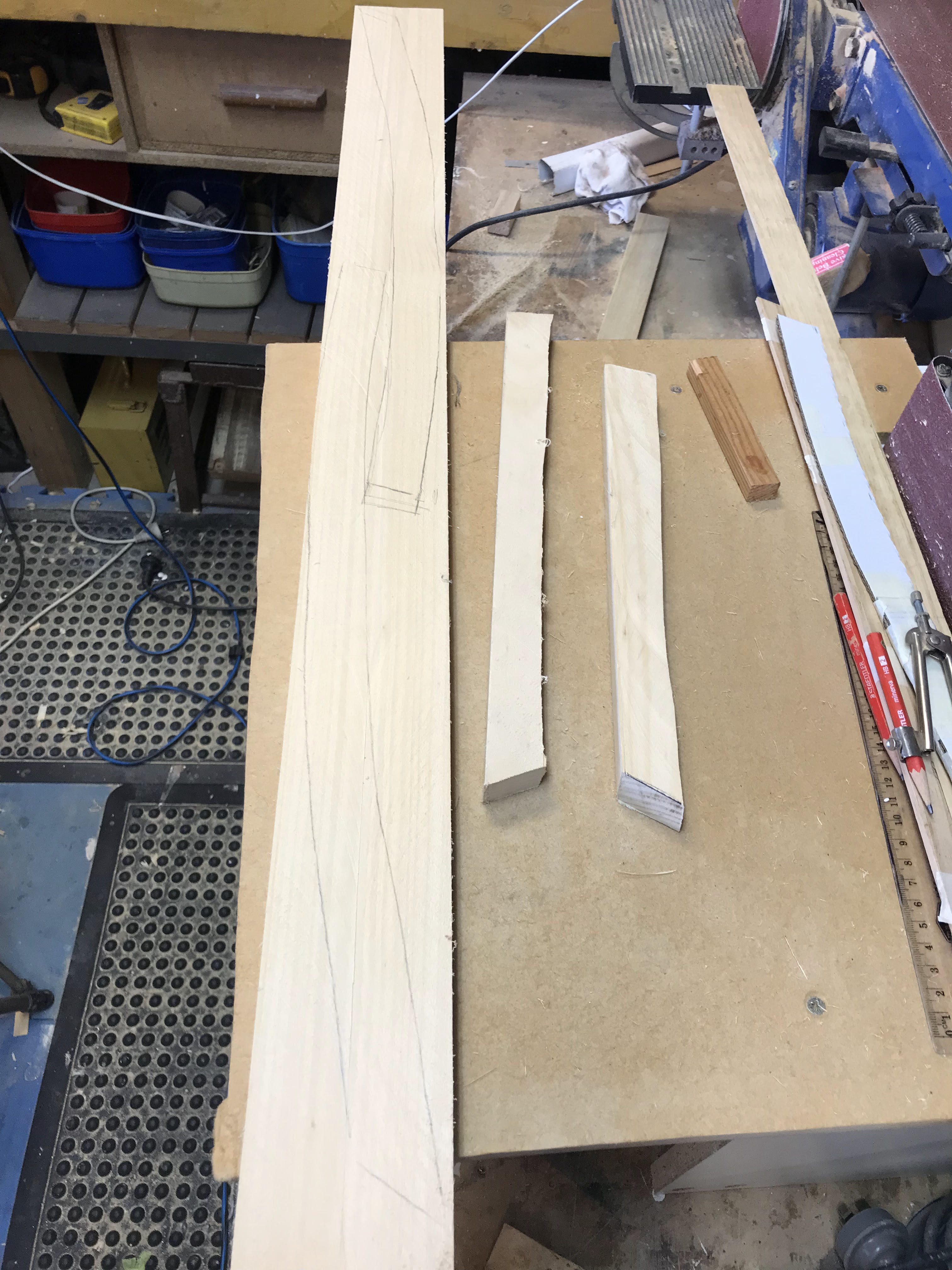
 I cut the upper cleat from a solid piece of Hoop Pine and followed the curves of the 
instruments. 


Here is the upper cleat fitted to the 9mm ply, edge routed and sanded should look very nice BUT.........I think it can be made to look nicer.


I decided to follow the laminated theme using the Blue Gum, yes more time-consuming work but it will look very nice inside the cabin.


I calculated the cuts for the laminations of alternating white Hoop Pine and Blue Gum that would evenly fill the upper cleat. This pic shows the two cuts in preparation for the lamination.


7mm thick Blue Gum strips are cut.


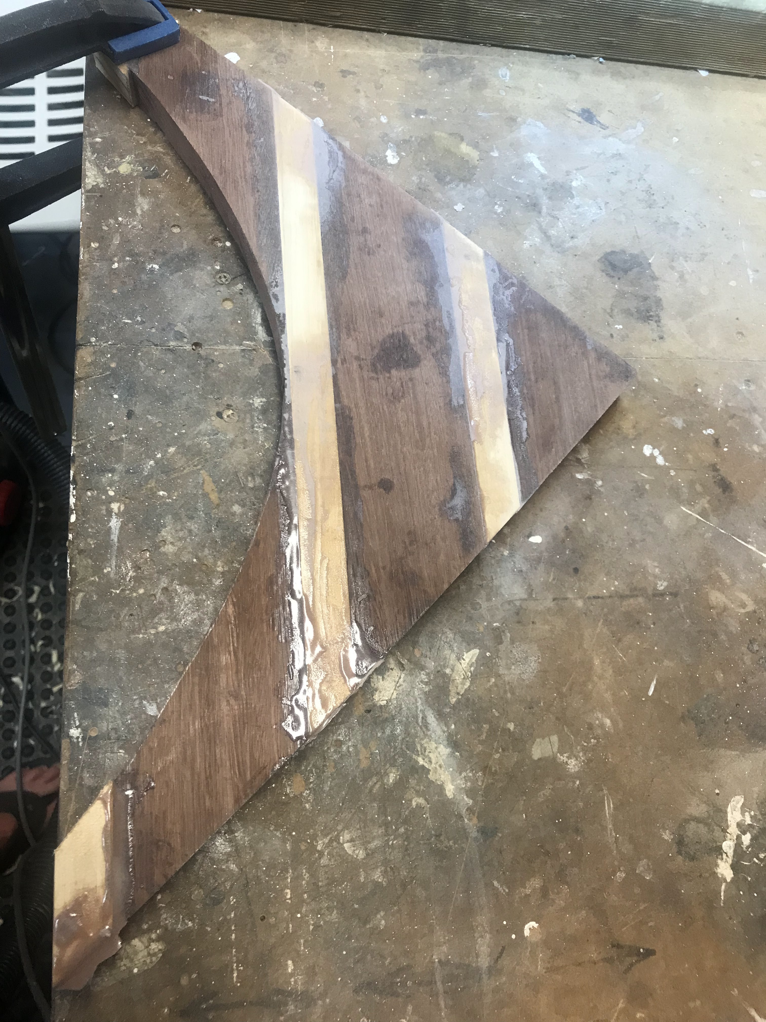
The 
sections are coated with epoxy and clamped together. A plastic sheet is placed under to prevent the piece sticking to the board.


The upper cleat will be left for 24 hrs. to set hard.


Time to clean up, I used 60 grit paper on an orbital sander.


Cleaned up in no time, looking nice.


A couple of coats of epoxy are applied before lacquering.


While waiting for the epoxy to dry I cut the two cabin top sheets from 6mm ply.


The two sheets are glued together in the middle with the butt block.


After consultation with fellow builders, I decided to strengthen the cabin top by glassing the underside. I hope it doesn't make it too stiff to bend into place.


The glass is wetted out with an overlap on the butt joint. 


Trial fit of the cabin top with a couple of clamps and three ratchet straps. It seems to be a good fit, plenty of overlap and conforms well to the cabin shape.


Using the little widget tool, I marked the location of the shearclamps, cleats and BH locations. This little tool worked a treat. 


The cabin top is temporarily screwed into place. I crawled inside the cabin and marked the location of the carlins, sheerclamps and cleats to the underside of the cabin roof ply.


As I am working on my own, I thought about a way to prevent the cabin top slipping and misaligning with the temporary screw holes.


So to ensure the cabin top aligns perfectly with the temporary screws holes I cut slots in the top ply adjacent to BH2 & BH3.


A piece of ply was temporarily screwed into the corner where BH2 joins the Dorade box. The piece aligned tightly with the slot cut into the cabin roof ply.


Two lengths of timbers are clamped to BH3 and tightly align with the aft slots of the cabin top. I’m now confident when I glue the cabin top down it will align perfectly with the screw holes. Well, that’s the theory……let’s see how it goes.


The top removed masked up and the first coat of polyurethane applied.


Looking good and this is only the first coat.


I also coated the carlins and cleats with polyurethane.

It’s now two years since construction commenced.


Monday, January 29, 2024

Laminated Upper Breast Hook

Here I go again another Mod.

Laminated Upper Breast Hook

 I decided to construct a laminated upper breasthook. Yes, as a retired old man I do have too much time on my hands, but the upper breasthook is a visually appealing section of the bow so let's make it a beautiful feature.

I used a combination of two contrasting-colored timbers, a red hardwood called Blue Gum (yes, a red colored timber called blue gum, go figure!) and a light-colored timber called Queensland Hoop Pine. I am also using the Blue Gum on the rub rails and Hoop Pine for the sheer rails, spars and cabin flooring so the timber types and colors will flow throughout the rest of the build.

I laminated the sections in situ on the build using plastic over the forward sheer clamps to prevent the breast hook from sticking to the sheer rails and the pieces held in place with clamps until the resin hardened.


When cured the breasthook will be shaped, routed and sanded prior to final fixing.


The laminated section is removed ready for sanding.


The breasthook is sanded top and bottom and the aft end is routed, its looking very nice.


The bottom is given a good saturation of epoxy prior to installation. The epoxy brought out the contrasting colors, I can't wait to see the upper surface when several layers of lacquer are applied. The astute may have noticed the groove in the bottom of the blue gum.... yes, what once was a floorboard is now a breasthook.


The unit is temporarily held in place with a single clamp and four 38mm SS screws.


Prior to gluing in place, I inserted 4 wires through the hull side into the screw holes. This is to ensure the holes line up and prevent splitting the timbers if the screw hole is missed.


The epoxied unit is clamped and screwed in place and left for a couple of days to set hard.


The breasthook is sanded down level with the sheer clamps and hull topsides, I think it turned out really nice. I can't wait to see the finished section when lacquered.


Saturday, January 20, 2024

Sheer Clamp Installation

 After a Christmas break it's time to get back into the build.

Sheer clamp and cabin carlin installation.

The sheer clamps and cabin carlins are milled from Hoop Pine. I like working with this timber, it has a fine grain no knots and is easy to work. I used Hoop Pine for the cabin flooring (see the March 2023 post titled "Floorboard Sealing and Installation"

To assist the installation of the sheer clamps and to enable the timber to bend around the hull without breaking or splintering I decided to steam the timbers.

I used the plastic pipe from my gutter blowing attachment, but any PVC storm water pipe would be OK. In my initial set up I used a kettle to send steam up into the plastic tube, but I found too much heat was lost through the thin plastic tubing and the kettle's thermostat kept turning it off so....


I replaced the kettle with a saucepan and wrapped old towels around the pipe to keep in the heat.

I placed the sheer clamps in the steamer for 2 hours.


Here you can see the steam exiting out the end of the pipe.


 The timbers were immediately clamped in place and left to dry overnight.


When removed a nice bend is left in the timber.


The sheer clamps are epoxied in place and left for a couple of days to cure. Lots of clamps were used to hold them in place.


Sunday, December 31, 2023

Cockpit Footwell Floor Installed

 Well, another small part of the project completed. 


I left the installation of the footwell floor to last to enable easy access to run the electrical wiring through the 25mm conduits. 

I also installed two extra athwartship cleats to provide additional support for the footwell floor.


The footwell floor was sealed on the underside and holes marked and drilled in place ready for the temporary screws.


The temporary holding screws are prepared, and the cleats are covered with epoxy glue.


Finally, the floor is secured in place.


Friday, December 29, 2023

Electricals

 Time to run some wires. 

When designing the wiring run, I considered the following:
1) I did not want wires visual in the cabin area.
2) The wiring harness needed to include power for the following: DC power outlets, cabin lights, Nav lights, stereo speaker, GPS/Fishfinder power and transducer, bilge pump and future solar power and motor charging wires.


I split the wiring into two conduits that run from BH2 under the floorboards to the junction boxes. The conduits run through the enclosed buoyancy area under the cockpit foot well. The conduits are sealed with silicon where they pass through BH's to ensure the buoyancy chamber is airtight. A further conduit was installed athwartships to link the two junction boxes. 


I made the junction boxes from 6mm ply. They are fully sealed units with clear Perspex fronts and screwed to the transom.


The wiring runs up into the port and starboard aft seat back storage areas and then forward through conduits to the main cabin.


To reduce voltage drop for DC power and the main earth connection I used larger diam wires (4.5mm diam) from BH2 through to the junction boxes in the lazarettes. The larger wires continued forward to the cabin area. As the cabin and Nav lights are all LEDS I reduced the wiring from the lazarette area to the forward cabin area to 2mm diam.

All wiring was twin core tinned marine grade and to reduce doubling up of negative wiring I only ran positives for the Cabin and Nav lights. I also ran nylon pull chords with the wiring harness so I could pull through any future wiring.

Thursday, December 14, 2023

Speaker Install

April 2023's post covered the construction of two ported speaker boxes built in the lazarette area aft of BH 8. Ports are used to produce a higher and deeper bass response (should make led Zeppelin sound pretty cool)

Time to install two GME (GS520 110 watt, 163mm Dia flush mount speakers.


Wires are run from BH 2 through conduit under the cabin floor to the electrical connection boxes on transom and then through to the speaker boxes in the lazarette area.


The boxes are filled with sound deadening/dampening wadding.


The speakers are screwed in place and the covers installed. can't wait to hear how they sound.